はじめに
前回の記事では、VSCodeのインストールや拡張機能、URDFのタグの説明をしました。

今回の記事では実際に車を記述していきます。
前提条件
前提条件は、以下の通りです。
- VSCodeがインストールされている
- VSCodeの拡張機能がインストールされている
URDFで車輪の記述
早速、車輪を記述していきます。
前回作成したfirst_robot.urdfを開き、中身を消して以下のコードを入力してください。
<?xml version="1.0" ?>
<robot name="rover">
<!-- main center object -->
<link name="base_link">
<visual>
<geometry>
<box size="0.4 0.35 0.075"/>
</geometry>
<material name="gray">
<color rgba="0.2 0.2 0.2 1"/>
</material>
</visual>
<inertial>
<mass value="2"/>
<inertia ixx="0.04" ixy="0.0" ixz="0.0" iyy="0.17" iyz="0.0" izz="0.25" />
</inertial>
<collision>
<geometry>
<box size="0.4 0.35 0.1"/>
</geometry>
</collision>
</link>
<!-- Robot Footprint -->
<link name="base_footprint"/>
<joint name="base_joint" type="fixed">
<parent link="base_link"/>
<child link="base_footprint"/>
<origin xyz="0.0 0.0 -0.075" rpy="0 0 0"/>
</joint>
<!-- front right wheel object -->
<link name="wheel_front_right">
<inertial>
<mass value="2"/>
<inertia ixx="1e-3" ixy="0.0" ixz="0" iyy="1e-3" iyz="0" izz="1e-3"/>
</inertial>
<visual>
<geometry>
<cylinder radius="0.075" length="0.05"/>
</geometry>
<material name="whtie">
<color rgba="1 1 1 1"/>
</material>
</visual>
<collision>
<geometry>
<cylinder radius="0.075" length="0.05"/>
</geometry>
<contact_coefficients mu="1" kp="1e+13" kd="1.0"/>
</collision>
</link>
<!-- front right wheel joint -->
<joint name="wheel_front_right_joint" type="continuous">
<origin xyz="0.125 0.2 0.0" rpy="1.57 0.0 0.0"/>
<parent link="base_link"/>
<child link="wheel_front_right"/>
<axis xyz="0.0 0.0 1.0"/>
</joint>
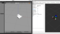
</robot>コード入力後、ctrl + shift + p でコマンドパレットを開き、URDFと入力してURDF Previewをクリックしてください。
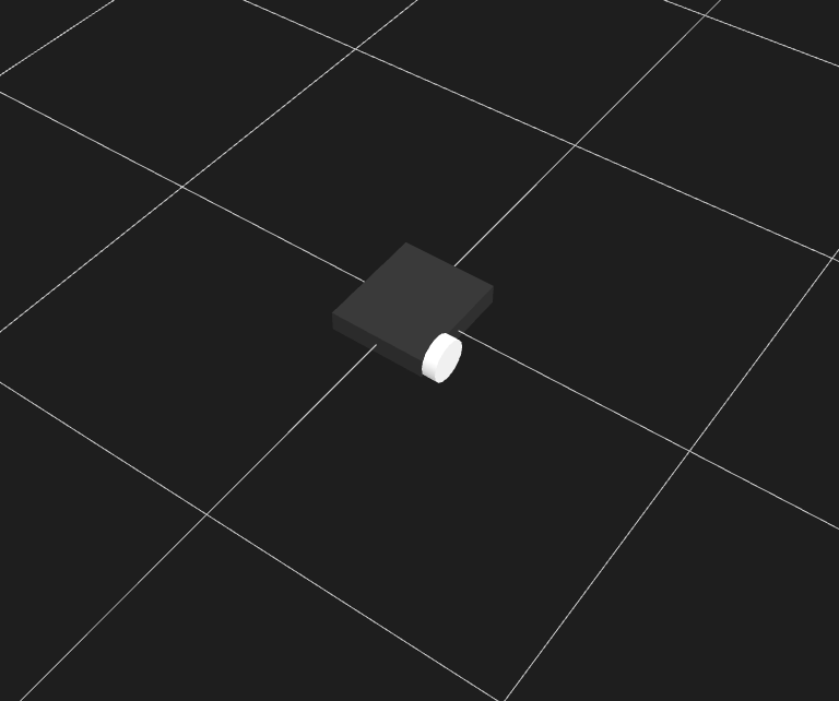
このように、表示されていればOKです。
コードの詳細を説明します。
<geometry>
  <cylinder radius="0.075" length="0.05"/>
</geometry>
こちらは、半径0.075 m 高さ0.05 m の円柱を示しています。
今回の車では車輪の半径の分だけbase_linkが上昇するので、
<joint name="base_joint" type="fixed">
  <parent link="base_link"/>
  <child link="base_footprint"/>
  <origin xyz="0.0 0.0 -0.075" rpy="0 0 0"/>
</joint>
このように、<origin xyz=”0.0 0.0 -0.075″>とすることで、base_linkをz軸方向に0.075m上昇させておきます。
次に、<collision>タグです。
<collision>
  <geometry>
    <cylinder radius="0.075" length="0.05"/>
  </geometry>
  <contact_coefficients mu="1" kp="1e+13" kd="1.0"/>
</collision>新しく<contact_coefficients>タグが登場しました。こちらは、ROSの公式サイトに説明があります通り、接触係数を表します。
- mu 摩擦係数
- kp 剛性係数
- kd 減衰係数
摩擦係数0で進むのかといったテストは別の記事で用意します。
最後に、<joint>タグについて説明します。
<joint name="wheel_front_right_joint" type="continuous">
  <origin xyz="0.125 0.2 0.0" rpy="1.57 0.0 0.0"/>
  <parent link="base_link"/>
  <child link="wheel_front_right"/>
  <axis xyz="0.0 0.0 1.0"/>
</joint>
車輪の回転に制限はないのでtype=”continuous”とします。
新しく<axis>タグが登場しました。type=”fixed”以外の結合タイプは回転方向を設定する必要があります。後に登場する「Rviz」というソフトを使用して回転方向を確認することができます。
URDFで二輪+補助輪の三輪車を描画
車輪と回転の説明をしたので、三輪車を描画します。コード全文を掲載します。
<?xml version="1.0" ?>
<robot name="rover">
    <!-- main center object -->
    <link name="base_link">
        <visual>
            <geometry>
                <box size="0.4 0.35 0.075"/>
            </geometry>
            <material name="gray">
                <color rgba="0.2 0.2 0.2 1"/>
            </material>
        </visual>
        <inertial>
            <mass value="2"/>
            <inertia ixx="0.04" ixy="0.0" ixz="0.0" iyy="0.17" iyz="0.0" izz="0.25" />
        </inertial>
        <collision>
            <geometry>
                <box size="0.4 0.35 0.1"/>
            </geometry>
        </collision>
    </link>

    <!-- Robot Footprint -->
    <link name="base_footprint"/>

    <joint name="base_joint" type="fixed">
        <parent link="base_link"/>
        <child link="base_footprint"/>
        <origin xyz="0.0 0.0 -0.075" rpy="0 0 0"/>
    </joint>

    <!-- front right wheel object -->
    <link name="wheel_front_right">
        <inertial>
            <mass value="2"/>
            <inertia ixx="1e-3" ixy="0.0" ixz="0" iyy="1e-3" iyz="0" izz="1e-3"/>
        </inertial>
        <visual>
            <geometry>
                <cylinder radius="0.075" length="0.05"/>
            </geometry>
            <material name="whtie">
                <color rgba="1 1 1 1"/>
            </material>
        </visual>
        <collision>
            <geometry>
                <cylinder radius="0.075" length="0.05"/>
            </geometry>
            <contact_coefficients mu="1" kp="1e+13" kd="1.0"/>
        </collision>
    </link>
    <!-- front right wheel joint -->
    <joint name="wheel_front_right_joint" type="continuous">
        <origin xyz="0.125 0.2 0.0" rpy="1.57 0.0 0.0"/>
        <parent link="base_link"/>
        <child link="wheel_front_right"/>
        <axis xyz="0.0 0.0 1.0"/>
    </joint>

    <!-- front left wheel object -->
    <link name="wheel_front_left">
        <inertial>
            <mass value="2"/>
            <inertia ixx="1e-3" ixy="0.0" ixz="0" iyy="1e-3" iyz="0" izz="1e-3"/>
        </inertial>
        <visual>
            <geometry>
                <cylinder radius="0.075" length="0.05"/>
            </geometry>
            <material name="whtie">
                <color rgba="1 1 1 1"/>
            </material>
        </visual>
        <collision>
            <geometry>
                <cylinder radius="0.075" length="0.05"/>
            </geometry>
            <contact_coefficients mu="1" kp="1e+13" kd="1.0"/>
        </collision>
    </link>

    <!-- front left wheel joint -->
    <joint name="wheel_front_left_joint" type="continuous">
        <origin xyz="0.125 -0.2 0.0" rpy="1.57 0.0 0.0"/>
        <parent link="base_link"/>
        <child link="wheel_front_left"/>
        <axis xyz="0.0 0.0 1.0"/>
    </joint>

    <!-- Caster Wheel -->
    <link name="front_caster" type="fix">
        <visual>
        <geometry>
            <sphere radius="0.075"/>
        </geometry>
        <material name="Cyan">
            <color rgba="0 1.0 1.0 1.0"/>
        </material>
        </visual>
        <collision>
            <geometry>
                <sphere radius="0.075"/>
            </geometry>
        </collision>
    </link>

    <joint name="caster_joint" type="fixed">
        <parent link="base_link"/>
        <child link="front_caster"/>
        <origin xyz="-0.15 0.0 0" rpy="0 0 0"/>
    </joint>

</robot>
first_robot.urdfへ上記コードを貼付し、保存してからURDF Previewで表示すると以下のようになります。
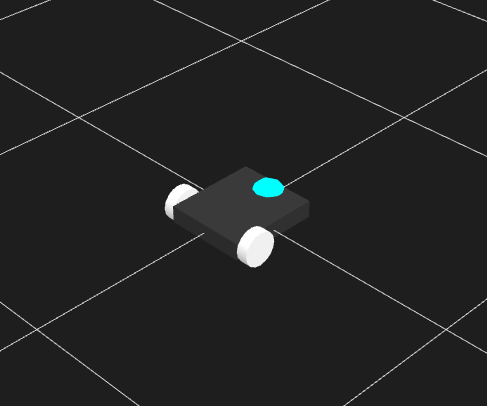
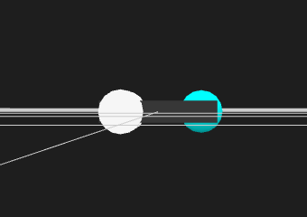
これで三輪車の形状は完成です。
ユニットを追加
これだけでは走ることしかできないので、少し形状を追加します。
first_robot.urdfの</robot>より上の行に以下を追加してください。
<joint name="caster_joint" type="fixed">
<parent link="base_link"/>
<child link="front_caster"/>
<origin xyz="-0.15 0.0 0" rpy="0 0 0"/>
</joint>
<!-- add camera object -->
<link name="camera_link">
<inertial>
<mass value="0.5"/>
<inertia ixx="0.01" ixy="0.0" ixz="0" iyy="0.01" iyz="0" izz="0.01"/>
</inertial>
<visual>
<geometry>
<box size="0.05 0.25 0.1"/>
</geometry>
<material name="blue">
<color rgba="0 0 1 1"/>
</material>
</visual>
</link>
<!-- add camera joint -->
<joint name="camera_joint" type="fixed">
<origin xyz="-0.175 0 0.1" rpy="0 0.0 3.14"/>
<parent link="base_link"/>
<child link="camera_link"/>
<axis xyz="0.0 0.0 1.0"/>
</joint>
<!-- add lidar object -->
<link name="lidar_link">
<inertial>
<mass value="0.5"/>
<inertia ixx="0.01" ixy="0.0" ixz="0" iyy="0.01" iyz="0" izz="0.01"/>
</inertial>
<visual>
<geometry>
<cylinder radius="0.05" length="0.05"/>
</geometry>
<material name="red">
<color rgba="1 0 0 0.7"/>
</material>
</visual>
</link>
<!-- add lidar joint -->
<joint name="lidar_joint" type="fixed">
<origin xyz="-0.215 0 0.0" rpy="0 0.0 1.57"/>
<parent link="base_link"/>
<child link="lidar_link"/>
<axis xyz="0.0 0.0 1.0"/>
</joint>
<!-- add imu object -->
<link name="imu_link">
<visual>
<inertial>
<mass value="0.3"/>
<inertia ixx="0.01" ixy="0.0" ixz="0" iyy="0.01" iyz="0" izz="0.01"/>
</inertial>
<geometry>
<box size="0.05 0.05 0.05"/>
</geometry>
<material name="green">
<color rgba="0 1 0 0.7"/>
</material>
</visual>
<collision>
<geometry>
<box size="0.05 0.05 0.05"/>
</geometry>
</collision>
</link>
<!-- add imu joint -->
<joint name="imu_joint" type="fixed">
<origin xyz="0 0 0.075" rpy="0 0 0"/>
<parent link="base_link"/>
<child link="imu_link"/>
<axis xyz="0 0 1.0"/>
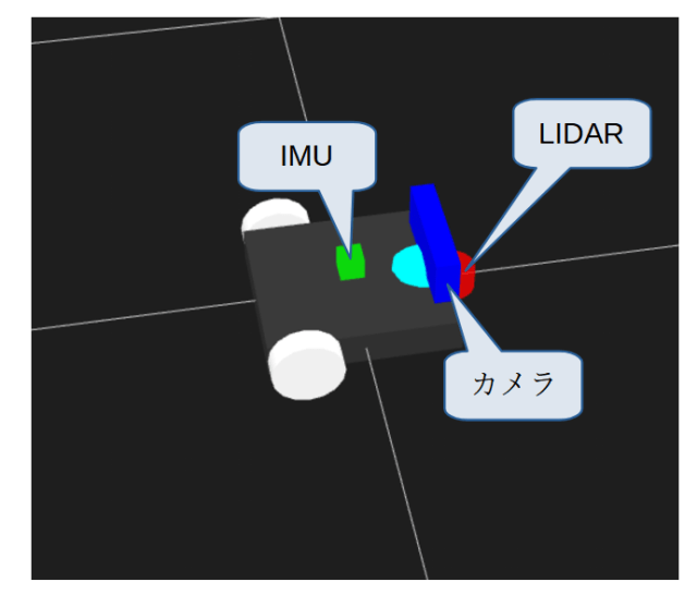
</joint>正常に追加できていれば、次のような表示になります。

IMU、LIDAR、カメラの詳しい説明は次回にします。
おわりに
URDFで胴体、車輪、カメラ、IMU、LIDARを描画しました。
特にIMUとLIDARは車体のコントロールに必要になってきますので忘れずに追記をお願いします。
次回はRviz2への表示とGazeboプラグインの解説までできればと考えております。

コメント